Example 4.3 models the temperature distribution in a turbine blade that is exposed to hot combustion gases on the outer surface and cooled internally by air flowing through an embedded channel. The blade cross‑section is discretized into a finite‑difference grid of 21 nodes, where each node represents a specific location in the blade material. Equal spacing of Δx=Δy=1 mm is used to simplify the finite‑difference formulation.
For each node, an energy balance is written that accounts for conduction to neighboring nodes and convection at surfaces exposed either to the hot gas (T∞,o=1700 K, ho=1000 W/m2K) or to the cooling air in the internal channel (T∞,i=400 K, hi=200 W/m2K). These node‑type equations follow the finite‑difference forms for interior points, convective surfaces, and corners given in the textbook’s 2‑D conduction chapter, and are assembled into a matrix system AT=C and solved in MATLAB to obtain the nodal temperatures
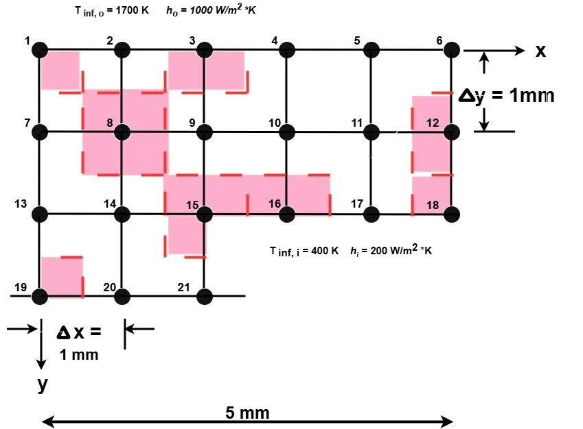
Figure 4 – Nodal network for Example 4.3